Difference between revisions of "LATA Switch"
Jump to navigation
Jump to search
(Imported from TWiki by twiki2mediawiki.py) |
(Imported from TWiki by twiki2mediawiki.py) |
||
| Line 3: | Line 3: | ||
--- |
--- |
||
| − | See also USB<->CAN documentation here: http://www.mictronics.de/projects/usb-can-bus/ |
+ | See also USB<->CAN documentation here: http://www.mictronics.de/projects/usb-can-bus/ (info on programing the hardware on these devices is here: [[USB-CAN]]) |
Key info from this doc is: |
Key info from this doc is: |
||
Revision as of 13:11, 30 June 2011
[[Image:LATA_protocol_small.jpg|]]
---
See also USB<->CAN documentation here: http://www.mictronics.de/projects/usb-can-bus/ (info on programing the hardware on these devices is here: USB-CAN)
Key info from this doc is:
TiiiiiiiiLDDDDDDDDDDDDDDDD[CR]
This command transmits an extended 29 Bit CAN frame. It works only if controller is in operational mode after command “O”.
- iiiiiiii Identifier in hexadecimal (00000000-1FFFFFFF) i.e. 100000BD in our example above
- L Data length code (0-8) i.e. 2 in example above
- DD Data byte value in hexadecimal (00-FF). Number of given data bytes will be checked against given data length code. e.g. 64 hex = 100% (i.e. on) and 00 hex is 0% (i.e. off) in our example above
Return: [CR] or [BEL]
---
- LATA CAN in minicom terminal:
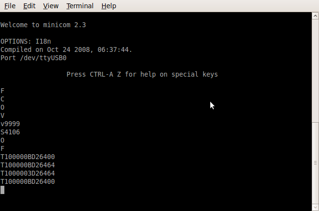

'V' - returns the version of the USB<->CAN device
'S4' - sets the comms rate (125K) Don't forget this!
'O' - sets the right mode
The fist byte is the Command:
- 100 (0x64) = CMD_SWITCH_TO
- 101 (0x65) = CMD_QUERY_CIRCUIT
- 102 (0x66) = CMD_PULSE
The 2nd byte in this example is either:
- 0x64 = 100% (i.e. on)
- 0x00 = 0% (i.e. off)