LATA Switch
See: http://sourceforge.net/projects/lata

---
See also USB<->CAN documentation here: http://www.mictronics.de/projects/usb-can-bus/ (info on programing the hardware on these devices is here: USB-CAN)
Key info from this doc is:
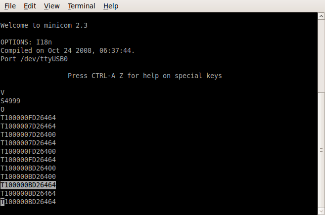
TiiiiiiiiLDDDDDDDDDDDDDDDD[CR]
This command transmits an extended 29 Bit CAN frame. It works only if controller is in operational mode after command “O”.
- iiiiiiii Identifier in hexadecimal (00000000-1FFFFFFF) i.e. 100000BD in our example above
- L Data length code (0-8) i.e. 2 in example above
- DD Data byte value in hexadecimal (00-FF). Number of given data bytes will be checked against given data length code. e.g. 64 hex = 100% (i.e. on) and 00 hex is 0% (i.e. off) in our example above
Return: [CR] or [BEL]
---
- LATA CAN in minicom terminal:
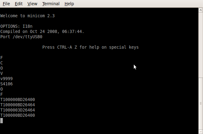

'V' - returns the version of the USB<->CAN device
'S4' - sets the comms rate (125K) Don't forget this!
'O' - sets the right mode
The fist byte is the Command:
- 100 (0x64) = CMD_SWITCH_TO
- 101 (0x65) = CMD_QUERY_CIRCUIT
- 102 (0x66) = CMD_PULSE
The 2nd byte in this example is either:
- 0x64 = 100% (i.e. on)
- 0x00 = 0% (i.e. off)
JF2 M2 Power + CAN CAT5 pins

LATA CANBUS terminator is a CAT5 plug with a 120 Ohm resistor between pins 1 and 2 (CANL and CANH).
- TechShowRoom:

Lata switch on dev kit at software freedom day:
T1000009D26464
T1000009D26400
T1800009D165
T1000009D26400