Difference between revisions of "Regulations"
(Imported from TWiki by twiki2mediawiki.py) |
(Imported from TWiki by twiki2mediawiki.py) |
||
| Line 356: | Line 356: | ||
In cases where the voltage of the power circuit exceeds 42 volt, this power circuit must be separated from the auxiliary circuit by an adequate insulator. Symbols warning of "High Voltage" must be |
In cases where the voltage of the power circuit exceeds 42 volt, this power circuit must be separated from the auxiliary circuit by an adequate insulator. Symbols warning of "High Voltage" must be |
||
| − | displayed on or near the electrical equipment protective covers; the symbols must comprise a black flash of lightning inside a yellow triangle with a black border. The sides of the triangle must measure at least 12 cm. |
+ | displayed on or near the electrical equipment protective covers; the symbols must comprise a black flash of lightning inside a yellow triangle with a black border. The sides of the triangle must measure at least 12 cm. [See [[High Voltage Sticker]] for a suitable design] |
* '''The power circuit''' consists of all those parts of the electrical equipment which are used for moving the vehicle. |
* '''The power circuit''' consists of all those parts of the electrical equipment which are used for moving the vehicle. |
||
* '''The auxiliary circuit''' (network) consists of all those parts of the electrical equipment which are used for signalling, lighting or communication. |
* '''The auxiliary circuit''' (network) consists of all those parts of the electrical equipment which are used for signalling, lighting or communication. |
||
Revision as of 20:29, 24 November 2008
NEDRA rule book - USA national electric drag racing association's rule book
http://www.fia.com/sport/Regulations/altregs.html
Key document (different versions from the last 3 years):
- 2006 - http://www.fia.com/resources/documents/839924369__Alternative_Tech_Reg_a.pdf
- 2007 - http://www.fia.com/resources/documents/1925697916__Tech_EnergieAlternative_2007.pdf
- 2008 - http://argent.fia.com/web/fia-public.nsf/6051D000A1613330C125741E004B0024/$FILE/R%C3%A8gleTech_EnergieAlternative_01.04.2008.pdf?Openelement
The following sections are pertinent extracts from the above 2006 doc (need to check for changes and update!):
1.1 Categories
Vehicles used in competition are classified as follows:
- Category I : Solar-powered racing vehicles
- Category II : Solar and/or electrically powered converted, modified and prototype vehicles
- Category III : Solar and/or electrically powered series production vehicles
- Category IIIA : Electrically powered Series Production Vehicles for daily use
- Category IV : Solar and/or electrically powered lightweight vehicles
- Category V : Electric single-seaters
- Category VI : Racing sports prototypes
- Category VII : Hybrid electrical vehicles
- Category VIII : Other alternative energy vehicles
1.2 Weight classes
The vehicles shall be divided up into the following weight classes (for definition see Article 3.1.1): 1. Vehicles with a weight of up to 150 kg (in Cat. V Class 1: Group 1 up to 270 kg, Group 2 up to 232 kg – driver included, see Article 7.12).
2. Vehicles with a weight of over 150 kg and up to 350 kg (in Cat. I and IV up to 300 kg). 3. Vehicles with a weight of over 350 kg and up to 500 kg. 4. Vehicles with a weight of over 500 kg and up to 750 kg. 5. Vehicles with a weight of over 750 kg and up to 950 kg. 6. Vehicles with a weight of over 950 kg and up to 1250 kg. 7. Vehicles with a weight of over 1250 kg and up to 1500 kg. 8. Vehicles which are able to carry at least one third of their weight as payload. Vehicles of Class 8 cannot start together with vehicles from other classes in the same racing group.
2.8 Racing sports prototypes (Category VI)
Open or closed four-wheeled vehicles with at least two seats (for racing purposes), with a weight of over 350 kg and not exceeding 1500 kg, and a minimum wheelbase of 1500 mm. Construction is free except that bodywork must cover all mechanical components when seen in plan view from above. For use on closed roads only. 2.8.A Specific Regulations for vehicles of Category V over Class 2 and Category VI over Class 2 The maximum permissible weight of a lead acid traction battery (40 Wh/kg) is limited to 50 % of the ready-to-start weight (see article 3.1.3) of the vehicle up to a maximum of 500 kg (20 kWh). If a different chemistry is used (see Table 1A) the weight of the traction battery has to be reduced accordingly to the ratio factor given in Table 1A. However, the use of a traction batteries with a higher energy density than lead acid batteries will not change the weight taken for the weight classification of the vehicle. For this weight classification a lead acid traction battery is assumed. Examples: A competitor using batteries with a higher energy density than lead acid batteries benefits from a reduced ready-tostart weight resulting in a better driving performance of the vehicle. Additionally, the lower vehicle weight aims an improved safety. The modification of the traction battery from lead acid to a more advanced battery technology like Ni-MH or Li-Ion will NOT change the weight classification of the vehicle. A newly built vehicle equipped with e.g. a Lithium-Ion traction battery will have a much lower ready-to-start weight than the weight taken for the weight classification. 1) Vehicle #1 has a weight wev of the empty vehicle without batteries of wev = 600 kg. Consequently, a traction battery weight wtr-batt of (up to) 500 kg is allowed resulting in a ready to start weight wRSW = wev + wtr-batt = 1100 kg. The vehicle will be classified in weight class 6 (over 950kg and up to 1250kg). 2) Vehicle #2 has a weight wev of the empty vehicle without batteries of wev = 450 kg. Consequently, a lead acid traction battery weight wtr-batt of up to 450 kg is allowed. If the competitor installs a battery with the maximum allowable energy value (18 kWh), the vehicle will be classified in weight class 5 (over 750 kg and up to 950 kg) regardless whether a Pb-Acid or e.g. a Li-Ion battery is used. For Li-Ion the traction battery weight wtr-batt will be 115,2 kg resulting in a ready-tostart weight wRSW = wev + wtr-batt = 450 kg + 115,2 kg = 565,2 kg. 3) Vehicle #3 has a weight wev of the empty vehicle without batteries of wev = 350 kg. Consequently, a lead acid traction battery weight wtr-batt of up to 350 kg (14 kWh) is allowed. If the competitor installs a smaller battery with an energy value of e.g. 8 kWh (200 kg Pb-Acid batteries), the vehicle will be classified in weight class 4 (over 500 kg and up to 750 kg) regardless whether a Pb-Acid or e.g. a Ni-MH battery is used. For Ni-MH the traction battery weight wtr-batt will be 111,2 kg resulting in a ready-to-start weight wRSW = wev + wtr-batt = 350 kg + 111,2 kg = 461,2 kg.
TABLE 1A Type of Battery Kart Batt. FIA-Rules from April 2005 Energy content for FIA Rules from April 2005 Ratio factor = weight of (other Bat.) / (Pb-Acid) Max. Batt. Weight for Cat. 5 & 6, Class 2 max [kg] [Wh/kg] [ ] [kg] Lead-Acid (Pb/Acid) 90 40,00 1,000 500 Nickel-Metal- Hydride (NiMH) 50 72,00 0,556 278 Nickel-Zinc (Ni/Zn) 52 69,23 0,578 289 Nickel-Cadmium (Ni/Cd) 72 50,00 0,800 400 Nickel-Iron (Ni/Fe) 72 50,00 0,800 400 Lithium-Ion 23 156,52 0,256 128 Lithium Metal Polymer 23 156,52 0,256 128 The FIA will publish this list periodically according to the state of the art of battery technology.
2.15 Vehicle technical passport
All vehicles participating in FIA events must have an FIA technical passport issued by the ASN and countersigned by the FIA Technical Delegate. Such technical passport containing an exact description of the vehicle along with all data necessary for the identification of the vehicle. The technical passport must contain drawings of the power circuits of the vehicle and their locations (see Article 4.6). The technical passport must contain a contingency plan for incidents involving the vehicle's battery, such as battery overheating or fire. The technical passport must be presented at scrutineering. The Stewards have the right to refuse to allow a competitor to take part in the event if the said competitor fails to submit the technical passport of the vehicle. It shall be the responsibility of the competitor to obtain the technical passport for the vehicle, along with any amendments or addenda to the said form, from the ASN/FIA. The responsibility for the data declared on the technical passport and for the enclosed drawings is up to the competitor.
ARTICLE 4 ELECTRICAL EQUIPMENT
4.1 Definitions
4.1.1) - Traction battery (storage battery)
A traction battery is the collection of all battery packs which are electrically connected, for the supply of energy to the power circuit. A battery pack is a single mechanical assembly optionally housed by a battery compartment, comprising battery modules, retaining frames or trays. A battery module is a single unit containing one cell or a set of cells electrically connected and mechanically assembled. A cell is an electrochemical energy storage device of which the nominal voltage is the electrochemical couple nominal voltage, made of positive and negative electrodes, and an electrolyte. The traction battery must be defined as any equipment used for the intermediate storage of electrical energy supplied by the solar generator or by the charging unit. The traction battery must be checked and sealed at scrutineering. The stewards may permit part, but not all, of the traction battery to be changed during the event, under the control of the chief scrutineer (e.g. a cell or a battery module). For Category V Class 1 vehicles (Electro-Karts), the complete traction battery may be changed during the race if the supplementary regulations allow (see Article 7.15). For Category V vehicles of Classes 5 and 6 (i.e., weighing over 750 Kilograms), batteries may be changed during the race provided the procedure has been approved by the chief scrutineer. Any on-board battery is considered as an integral part of the vehicle's traction battery. All on-board electrical equipment, unless consisting of items originally powered by dry batteries, small rechargeable batteries or their own solar cells, must receive its energy supply from the vehicle's traction battery (this also applies to communications equipment). The following battery types are permitted: - Lead-Acid - Nickel-Cadmium - Nickel-Iron - Nickel-Zinc - Zinc-Bromium - Nickel-Metal-Hydride - Lithium-Ion Exception: For Category V Class 1 vehicles (Electro-Karts) no high temperature batteries such as Zinc-Bromium are allowed. Request for additions to this list must be sent to the commission 3 months in advance, giving full details of chemistry. A fee may be required. Batteries, more than 5% of whose weight consists of gold, silver or platinum, are not allowed. Exception: In Category I and Category V, Class 1, the event organiser may create a separate group for vehicles with such batteries.
4.1.2) - Operating voltage
The voltage is limited to 1000 volts (for Category V Class 1 vehicles 200 volts) between two points (see Article 5.13 for safety provisions).
4.1.3) - Energy capacity of the traction battery
The capacity C1 is the capacity of the battery in Ah at a battery temperature of 25°C and for a complete battery discharge within a maximum of 1 hour. The capacity C5 is the capacity of the battery in Ah at a battery temperature of 25°C and for a complete battery discharge within a maximum of 5 hours. The capacity C20 is the capacity of the battery in Ah at a battery temperature of 25°C and for a complete battery discharge within a maximum of 20 hours. The energy is calculated as the result of the product of the nominal voltage of the vehicle's traction battery in volt and the capacity C5 in Ah. The energy capacity must be expressed in kWh.
4.1.4) - Charging the traction battery
The vehicle's traction battery must be charged at the times and locations determined by the organiser of the event. Vehicles in Categories II to VI and VII (if applicable) must recharge their batteries at the mains recharging station ("grid compounding station"). By day between 08.00 and 20.00, the minimum charging time will be 1 hour and the maximum charging time 4 hours. By night, between 20.00 and 08.00, the minimum charging time will be 8 hours. Delayed arrival at the grid compounding station will be at the expense of the participant. An example of a vehicle park around a grid compounding station is shown in figure n° 4.
4.1.4.a) - Measurement conditions of the maximum voltage
The maximum voltage has to be measured at least 15 minutes after end of charging of the traction battery.
4.1.5) - Energy recovery
It is permitted to recover energy generated by the kinetic energy of the vehicle. It is not permitted to have stored energy in such devices before the start of the event.
4.1.6) - Use of outside energy sources
The use of any other source of energy in any form whatsoever with the aim of improving the performance of the vehicle is strictly prohibited. The cooling system must be driven only by the vehicle's official traction battery (except in Category VII and VIII).
4.4 Charging units
For vehicles of categories II to VII, charging units must be carried on board the vehicle for the duration of the event. Exceptions: On board charging units are not compulsory for Category IV, Category V, and Category VI and in circuit races or in closed roads also not compulsory for vehicles of Category II. Except for Category V Class 1, the charging units and the cables must be in compliance with IEC 718 (for details see Article 2.18). It is mandatory to use a double wound transformer with electrical separation for the charging unit (galvanic insulation). Except for Category V Class 1, the charging unit must be checked and sealed at scrutineering. It must therefore be presented for scrutineering. A penalty, which may go as far as exclusion from the event, will be imposed for charging a battery with a charging unit which has not passed scrutineering. In Categories II and III the charging unit must be fitted with at least 5 m of flexible cable, not necessarily in one piece, and a plug complying with the regulations. This cable must be carried on board the vehicle throughout the duration of the event. Additionally, the competitor must bridge the distance to the official assigned charging socket supplied by the organiser by means of a reel device extension cable complying with the regulations, with a minimum length of 20 m. A label made from durable material must be affixed in an easily accessible location on the charging unit and must permanently display the name of the manufacturer, the nominal power, the type (model) of the charging unit and the nominal voltage (see IEC 718 Article 2.18). It must be ensured that the vehicle can only be restarted once the mains plug of the charging unit has been reconnected to a coupling mounted on the vehicle.
4.5 Charging from the mains
For each vehicle designed for mains power charging, there must be an officially assigned mains power connection (socket) at the grid compounding station. The socket and the plug of the charging unit cable of the vehicle must be marked during the event with the starting number of the vehicle. Schuko-sockets (German-system) or EEC sockets (IEC 309-2 standard) will normally be used (see figure n° 6), the organiser must publish the kind of sockets in the latest communication. Each socket must be protected by a corresponding automatic fuse (see current of the charging unit) and an automatic ground fault current interrupter (FI) with 0,03 Ampere release current. During possible random checks the mains voltage and current consumption will be measured with a volt- and an ampere-meter at the official socket of the vehicle at the grid compounding station over a period of 1 to 2 minutes. In cases where the effective (root-mean-square) mains current ('Ieff') of the charging unit exceeds the following maximum values, measured at the official socket of the vehicle at the grid compounding station, the competitor shall be fined. Exception: in Category V Class 1 no measurements will be made. TABLE 3 Nominal mains voltage Effective mains current (Ieff) for Classes 1 to 8 100 volt to 130 volt 32 ampere 200 volt to 250 volt 16 ampere Exception: In circuit races, if the Supplementary Regulations so permit, vehicles in Category II, V, and VI, weight classes over 750 kg, are authorised to recharge their traction battery by means of two official sockets. Each socket may supply a maximum mains current value taken from table 3 above. The charging energy obtained from the grid compounding station must be measured in all events where an energy classification is established and may be measured for races by the organiser using energy meters (counter). An official is required to monitor the grid compounding station continuously. Where a vehicle's battery is charged by means of a socket other than the official assigned socket or by means of a socket belonging to another competitor, the guilty competitor shall be penalised.
4.6 Electrical drawings
One electrical drawing (A4, 21 x 29,7 cm) of all the essential power circuits of the electrical equipment of the vehicle is compulsory. This circuit drawing must contain batteries, fuses, circuit breakers, power switchers, capacitors, motor-controller or chopper, motor(s), charging unit and junction cables. All components in the circuit drawing must be labelled with their detailed electrical specifications. A second drawing of the vehicle in plan form (from above) must show the location of these components within the vehicle. Both said electrical drawings are an integral part of the vehicle technical passport.
5.3 Cables, lines and electric equipment
Brake lines, electrical cables and electrical equipment must be protected against any risk of damage (stones, corrosion, mechanical failure, etc.) when fitted outside the vehicle, and against any risk of fire when fitted inside the bodywork. If the series production fitting is retained, no additional protection is necessary.
5.7 Fire extinguishers, fire extinguishing systems
Fire extinguishers and fire extinguishing systems are not compulsory for Categories I, IIIA, IV and V. Fire extinguishers in compliance with Article 253.7.4 of the ISC Appendix J (only powder 2 kg for AB or ABC fire fighting) are compulsory for all others.
5.13 Electrical safety
All vehicles must comply exactly with the regulations of the national authorities with regard to the standardisation and control of low-voltage electrical installations (see Article 4.1.2, regarding the operating voltage). Likewise, but with the exception of Category V Class 1, the regulations of the IEC (Commission Electrotechnique Internationale) (e.g. IEC 529, 718, 783, 784, 785, and 786), or of the national representative or member f the IEC (e.g. VDE/SEV), must be observed. In no part of the electrical equipment may there be voltages of more than 500 volts referred to earth (200 volts for Category V Class 1) and system ground respectively system ground is the ground of the electrical equipment). Between system ground and chassis or body of the vehicle no more than 50 volts are allowed. The voltage is limited to 1000 volts between two points (200 volts for Category V Class 1).
In cases where the voltage of the power circuit exceeds 42 volt, this power circuit must be separated from the auxiliary circuit by an adequate insulator. Symbols warning of "High Voltage" must be displayed on or near the electrical equipment protective covers; the symbols must comprise a black flash of lightning inside a yellow triangle with a black border. The sides of the triangle must measure at least 12 cm. [See High Voltage Sticker for a suitable design]
- The power circuit consists of all those parts of the electrical equipment which are used for moving the vehicle.
- The auxiliary circuit (network) consists of all those parts of the electrical equipment which are used for signalling, lighting or communication.
All parts of the electrical equipment must be protected using at least IP 44 type protection (dust proof and splash proof). However, it is recommended that IP 55 type protection be used (fully dust proof and water stream proof) (see e.g. IEC 529 Article 4.2). Exception: It must be ensured for Category V Class 1 vehicles that the components used for protecting persons or objects can reliably fulfil their function for an appropriate length of time even under wet weather conditions and without reducing the electrical safety level (proper insulation and housing!).
5.13.1) - General circuit breaker, "Emergency stop"
When seated in a normal and upright position, with the safety belts fastened and the steering wheel in place, the driver must be capable of interrupting all electrical transmission between the traction battery and the energy consumers (see figure n°9) by means of a spark-proof general circuit breaker ("Emergency stop button") located within the driver's normal field of vision. The button must be located in such a way that it can also be operated from outside the vehicle. The general circuit breaker must consist of a red button and a yellow disc of at least 8 cm in diameter reading "Emergency" in red or black letters. For closed vehicles, the external button of the general circuit breaker must be located below the windscreen on the driver's side, i.e. on the left-hand side of the vehicle when facing in the direction of travel. For open vehicles, (except Category V Class 1) the external button of the circuit breaker must be located on the left-hand side at the base of the main rollbar structure when facing in the direction of travel. The button must be identified by a red flash of lightning inside a blue triangle with a white border. The sides of the triangle must measure at least 12 cm In order to prevent contact melting of the general circuit breaker its [I²t] (ampere square seconds characteristics, representing heat energy dissipated on the breaker contacts during switching) must be sufficient to guarantee proper operation of the circuit breaker, even under surge current conditions, in particular those occurring during the connection of the traction battery to the power bus. A device, e.g. the general circuit breaker, must prevent movement of the vehicle whenever the driver is not fully seated in the driver´s seat.
5.13.2) - Overcurrent trip (fuses)
5.13.2.1 - Definitions
An overcurrent trip is a device which automatically interrupts the electrical current in the circuit in which it is installed if the level of this current exceeds a defined limit value for a specific period of time. Fuses and circuit breakers (but never the motor circuit breaker) count as overcurrent trips. (Extra fast electronic circuit fuses and fast fuses are appropriate). The fuses must be in an easily accessible location and as close as possible to the traction battery at both polarities (see figure n°9).
5.13.2.2 - Electrical cables
All electrical cables inside the vehicle must be protected by means of over currents trips rated according to the diameter of the individual conductors. Overcurrent trips must under no circumstances replace the circuit breaker (emergency stop button).
5.13.3) - General electric safety
It must be ensured that the components used cannot cause injury under any circumstances, either during normal operation or in foreseeable cases of malfunction. It must be ensured that the components used for protecting persons or objects can reliably fulfil their function for an appropriate length of time.
5.13.3.1 - Insulation resistance
Every part of the electrical equipment must have a minimum insulation resistance between all live components and earth. - For equipment with up to 300 volt to earth, the insulation resistance must reach the following value: 250 k Ohms. - For equipment with more than 300 volts to earth, the insulation resistance must reach the following value: 500 k Ohms. The measurement of the insulation resistance must be carried out using a d.c. voltage of at least 100 volts.
5.13.3.2 - Dielectric strength
All electrical equipment of the vehicle conducting electrically must fulfil the following conditions: With regard to dielectric strength, a distinction must be made between material with light, normal or reinforced insulation. Normal insulation is insulation which can withstand a test voltage of at least 2000 volts (1000 volts for Category V Class 1) at 50 hertz for a period of one minute. It must only be used for electrical circuits with a nominal voltage not exceeding 500 volts. Reinforced insulation is insulation which can withstand a test voltage of at least 4000 volt at 50 hertz for a period of one minute. It must only be used for components with a nominal voltage not exceeding 1000 volts. Light insulation must not be used (except for the auxiliary circuit). All electrically live parts must be protected against accidental contact. Insulating material not having sufficient mechanical resistance, i.e. paint coating, enamel, oxides, fibre coatings (soaked or not) or insulating tapes are not accepted. All electrically conducting non live parts must be connected with the vehicle ground.
5.13.4) - Capacitors
Voltage across capacitors belonging to the power circuit should fall below 65 volts within 5 seconds after the general-circuit breaker is opened or the over current trips of the traction battery are blown.
5.14 Battery fastening
The traction battery must not be installed in the cockpit. It must be installed securely inside the vehicle and be protected against short-circuits and leakage by means of a battery compartment. This compartment must completely surround the batteries. It must be made from an insulating, resistant and battery fluid–tight material. The batteries housed in the battery compartment must be attached to the body using metal clamps with an insulating covering, fixed to the floor by bolts and nuts (bolts with a diameter of at least 10 mm). The fastening must be designed in such a way that neither the battery nor the fastening device itself nor its anchorage points can come loose, even when subjected to a crash. The manufacturer of the vehicle has to prove, by whatever means, that the attachment of the battery and the battery compartment can withstand the same stresses as those introduced in the paragraph concerning the safety rollbar (see Article 5.8). The battery compartment must be designed in such a manner as to prevents short circuits of the battery poles and of the conductive parts, and any possibility of battery fluid penetrating into the cockpit must be excluded. A solid partitioning bulkhead must separate the location of the battery from the cockpit.
Each battery compartment located inside the vehicle must include an air intake with its exit outside of the vehicle. On each battery compartment symbols warning of “High Voltage” must be displayed (see Article 5.13).
---
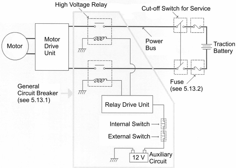
It is strongly recommended to use of power circuit as detailed in the scheme equipped with two “High Voltage Relays” or a single “High Voltage Relay” with two separate contacts for both traction battery polarities. A single relay with only one contact breaker is not recommended.
- Recommended contact breaker circuit:

From the 2008 doc:
Appendix 4c - Example of Circuits to protect against Electrical Shocks
For a description see Articles 2.15 and 5.2.1. A high input impedance measurement electronics checks the isolation resistance Riso between earth (chassis) potential and system ground of the solar car. In case of alfunction (Riso < 100 kΩ) resulting in a possible error current Ierror of more than 5 mA the measurement device cuts off the power from the solar array and from the traction battery by means of the general circuit reaker (Emergency Stop) and by means of the solar panel circuit breaker.